Power Over Ethernet Cable Explained in Easy Steps
What Is PoE?
The abbreviation PoE stands for “Power over Ethernet.” In a network cable (twisted pair) with a 100BASE-T connection (Fast Ethernet, 100 Mbit/s), data is transmitted only in 2 pairs, and the remaining 2 pairs remain free. One day someone came up with the idea of using these free conductors to supply power to devices.
The equipment receives both data and electricity via one LAN cable. It is very convenient for those cases when the equipment needs to be installed on the roof, on the mast, in the courtyard of a private house, that is, in those places where it is problematic or expensive to supply a separate cable with power supply. Devices that perform the functions of a step-down transformer and a rectifier must be present in a PoE network.
What is PoE for?
Connecting devices in hard-to-reach places. For example, there are only two electrical outlets for the monitor and the system unit at the user’s workplace. Often such requirements do not appear due to an error in planning but are dictated by the industry, regional and other standards of IT security, fire safety, occupational safety, and so on.
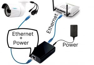
Another example is if a video camera or access point is fixed under the ceiling, it can be difficult to stretch the power cord there as well.
Power Management
The second advantage is that PoE allows you to control the device using power, for example, temporarily turn it off, turn it on or restart it (when it freezes, updates, or other needs). This is convenient if you have to work remotely or when the devices are in hard-to-reach places.
This is especially useful when working with access points that can be located at a considerable distance or even hidden somewhere above the ceiling.
Facilitate Maintenance
In addition to ease of operation, the use of PoE allows you not to bother with the purchase and repair of power adapters, providing users with outlets, for example, through the purchase of a PDU (Power distribution unit). Fewer nodes — fewer points of failure — fewer calls to technical support.
Electrical Safety
No matter what anyone says, 120 Volts (or 220V) is a lot. It hurts, it kills. But 57 volts, which is the maximum for PoE, is also unpleasantly dangerous, but not so much anymore. In some organizations, in order for the sysadmin to do the work of an electrician, a special permit is needed. And organizations have no problems with PoE.
Aesthetics
What do the technical staff need first? If only all the equipment would work. But some people need it to be beautiful as well. For example, so that extra wires do not hang down. Or to have all the wires of the same color. And PoE gets rid of these extra wires. All kinds of inspectors, commissions, and big bosses are particularly attentive to this.
PoE Devices
PoE devices are divided into several types:
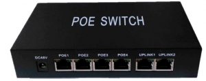
- Endspan switches and routers with PoE support. When a network device is connected to such a switch, it will receive power automatically — unless, of course, it also supports PoE.
-
Midspan — PoE adapters (injectors) and PoE power supplies. These devices are used when you need to organize PoE on separate network lines. They allow you to connect PoE consumers to conventional switches.
-
Splitters are devices designed to connect conventional network devices to a PoE network. They separate the incoming power and data via one cable, outputting them to two separate connectors: RJ-45 and the power connector.
A PoE injector and a PoE splitter in a pair can be used to transmit power over an Ethernet cable in a conventional network without PoE-enabled devices. -
PoE endpoint devices are network devices (IP phones, video cameras, access points, switches, etc.) capable of receiving power over an Ethernet network.
How does PoE Work?
PoE technology uses two modes of data transmission over a twisted pair, called A mode and B mode. According to method A, power is transmitted via the same wires as the data (1,2,3, and 6 pins in the connector). According to the “B” method, power is transmitted via other wires — 4,5,7, and 8.
In 10Base-T and 100Base-TX networks (10 Mbit and 100 Mbit, respectively), these wires are not involved, which allows you to use an inexpensive four-wire cable. Obviously, the “B” mode will not work with such cables.
All PoE endpoints and splitters can work in both ways. But power supplies, as a rule, support only one mode.
Thus, if you have a 10Base-T or 100Base-TX network built on a four-wire cable, the power supplies must support mode “A .”Unfortunately, it is not so easy to determine which mode is supported by the source.
For some reason, this is often overlooked in the specification, and sometimes it is possible to determine the mode only by documentation or by a sticker on the equipment case. If the installers indicated pins 1-2-3-6 there, then the power is supplied according to mode “A,” if 4,5,7,8 — according to mode “B.”
If you use an eight—wire cable in the LAN, you can not think about the PoE mode – any PoE equipment will work on such cables.
Those unfamiliar with the technology often ask the question: is it dangerous to connect ordinary devices to a PoE network without PoE support?
This is safe — the injector will supply power to the cable only after it receives a response about protocol support from the powered device. This protects the equipment from damage not only when PoE is not supported but also if the network cable was crimped incorrectly.
However, there is Passive PoE technology, in which the power transmission over the cable is carried out by a pair of separate devices. The injector connected to the power supplies voltage to unoccupied pairs, and the splitter removes it and outputs it to a separate connector (socket) to which ordinary network equipment is connected.
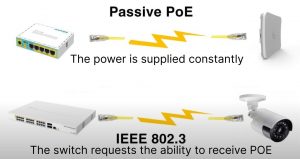
The Passive PoE injector supplies power to the cable immediately after switching on. And if on the other side of the cable you connect not a Passive PoE splitter but a network device directly, it may fail. Well, an error when crimping the cable, in this case, can also lead to unpleasant consequences.
Passive PoE can simplify (and reduce the cost) of connecting conventional network devices without introducing PoE into the local network, but it should be used with caution. In addition, since Passive PoE can only transmit power over unoccupied pairs, it cannot be used in 1000Base-T networks.
Advantages and Disadvantages
PoE-enabled equipment is more expensive than usual, so in some cases, there will not be much savings. For example, when building an IP telephony network – as a rule, there are already sockets at the phone installation points. But the benefits of using PoE can be not only economic.
Connecting devices via PoE is safer since the twisted pair power supply is stabilized and does not depend on interference in the 110-220V network. And with the help of PoE, it is very easy to provide all network devices with a guaranteed power supply. For this, you just need to power the base network hub from the UPS (of course, both it and network devices must have PoE support).
PoE provides centralized management and control of all network devices: switching on/off of each individual device (including automatic), keeping records of the electricity consumed by each device; the interface of PoE hubs usually also allows you to determine the operating mode of individual devices and detect breakdowns in a timely manner.
Connection using PoE looks aesthetically more perfect — fewer sockets, fewer wires.
The disadvantages of devices with PoE (in addition to the already mentioned high price) include limited electrical power and an increased level of energy loss: the cross-section of the twisted pair conductors is small, so the resistance increases and the voltage drops. In addition, due to the greater power of the PoE-enabled hub, it will need a more powerful (and expensive) UPS.
PoE Standards
For beginners, there may be some confusion. There are 3 generations of the standard:
First-generation PoE (IEEE 802.3af standard) provides power up to 15.4W DC for each connected device.
The second-generation IEEE 802.3at standard, also called PoE+, can output up to 30 watts of power for each device. This standard is used to power more demanding consumers, for example, Pan-Tilt-Zoom (PTZ) surveillance cameras and 11n wireless access points.
For simplicity, the main differences are summarized in the table:
| Property | 802.3af (802.3at Type 1) “PoE” | 802.3at Type 2 “PoE+” | 802.3bt Type 3 “4PPoE” | 802.3bt Type 4 |
| Power available at PD | 12.95 W | 25.50 W | 51 W | 71 W |
| The maximum power delivered by PSE | 15.40 W | 30.0 W | 60 W | 100 W |
| Voltage range (at PSE) | 44.0–57.0 V | 50.0–57.0 V | 50.0–57.0 V | 52.0–57.0 V |
| Voltage range (at PD) | 37.0–57.0 V | 42.5–57.0 V | 42.5–57.0 V | 41.1–57.0 V |
| Maximum current Imax | 350 mA | 600 mA | 600 mA per pair | 960 mA per pair |
| Maximum cable resistance per pairset | 20 Ω (Category 3) | 12.5 Ω (Category 5) | 12.5 Ω | 12.5 Ω |
| Power management | Three power class levels (1-3) negotiated by signature | Four power class levels (1-4) negotiated by signature or 0.1 W steps negotiated by LLDP | Six power class levels (1-6) negotiated by signature or 0.1 W steps negotiated by LLDP | Eight power class levels (1-8) negotiated by signature or 0.1 W steps negotiated by LLDP |
| Derating of maximum cable ambient operating temperature | None | 5 °C (9 °F) with one mode (two pairs) active | 10 °C (20 °F) with more than half of bundled cables pairs at Imax | 10 °C (20 °F) with temperature planning required |
| Supported cabling | Category 3 and Category 5 | Category 5 | Category 5 | Category 5 |
| Supported modes | Mode A (endspan), Mode B (midspan) | Mode A, mode B | Mode A, mode B, 4-pair mode | 4-pair mode |
(Source: Wikipedia)
The third generation is described by the IEEE 802.3 standard.
Devices of the third generation of PoE allow you to provide a power supply with a capacity of up to 51 watts via a single cable.
To power devices using IEEE 802.3 bt standard technologies, all eight conductors of a modern twisted pair cable (cat 5 and higher) are involved, while only four can be dispensed with for the first two generations.
If we talk about compatibility, then PoE devices are backward compatible — a more powerful 802.3bt power supply device can be used for older PoE and PoE+ consumers (802.3af and 802.3at).
PoE Pinout
For the 802.3af standard, Type A.
Both electricity and data are supplied via conductors 1, 2, 3, and 6. Conductors 5, 7, and 8 are not used.
Type B. Conductors 4, 5, 7, and 8 are used to supply power. Data is transmitted over the rest. For the 802.3at standard, only Type B is used. The use of pinout type A is prohibited by the standard.
For Passive PoE: In most cases, the power supply is carried out via conductors 4, 5, 7, 8 (as in type B of the 802.3af standard).
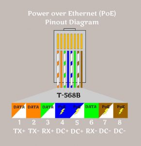
There is also a pinout of the third type when all the conductors of a standard four-pair cable are used to supply power, but it is less common, usually in proprietary PoE implementations, for example, UPOE from Cisco.
If you install equipment with support for 802.3af/802.3at standards on both sides of the network, then the type of pinout does not actually matter since the PoE consumer device can work with any of them according to the standard. However, if we are talking about combining equipment of different standards, this may be important.
What Is Important to Know for Proper Connection
So we bought some kind of PoE adapter, connected it to Ethernet, and the power grid then connected the LAN cable from it to the access point that we wanted to power. It seems simple. Only the access point burned down for some reason. Why would that be? In order to properly organize a remote PoE connection, several important factors must be taken into account:
- The type of power supply provided by a PoE switch or injector: Which standard does it meet? What is the mains voltage? What type of pinout?
- The voltage that our equipment needs.
- Distance to the remote point.
These initial data will help you choose PoE equipment that is compatible with each other and calculate the possibility of a remote power supply. If this is not done, the connected equipment will quickly fail or will not turn on at all.
What are the cable requirements?
For connection, when powered via PoE, a twisted pair of at least cat5e is used.
Important! The conductors must be copper, not copper-plated, with a thickness of at least 0.51 mm (24 AWG). The resistance in the conductors should not exceed 9.38 ohms/100 m.
Usually, in practice, it is recommended not to use cables longer than 75m, although the 802.3af and 802.3at standards speak of support for 100m. In the case of Passive PoE, the practical recommendations are even more stringent — the actual cable length for normal operation should not exceed 60m.
However, special switches, for example, managed by GS1350 Extended Range Essentials, can support devices at a distance of 250m at a speed of 10Mb/s.
And finally, the answer to the question: which devices to choose?
Choosing a Power Supply Device
When they talk about choosing a source device for PoE power, I mean endspan, and usually, it is a switch. The switch is the most used option. They are used in IP telephony, video surveillance, and when installing access points, and when arranging all kinds of sensors of security systems, ACS controllers, and so on.
It is important to take into account several factors:
- Top-down compatibility. That is, a more modern device that supports the latest IEEE 802.3af standard can be used to connect and power older devices. But on the contrary — no.
- The remoteness of PD (powered devices). If, for example, the warehouse area is expanding or the office is scheduled to move. It is better to future-proof.
- Device management. In addition to the option to manually turn off-turn on the power of the switch, there are other control options, for example, using the LLDP protocol for video cameras.
- Protection against surge and other harmful factors.
How to Choose the End Device
Usually, when choosing end devices, they focus on their technical characteristics, for example, the quality of the video camera image, support for Wi-Fi standards when choosing access points, and so on.
However, the power supply also needs to be considered:
- The efficiency of the device.
- Management capabilities.
- Price and quality.
Important! Despite the declared compatibility, you should not rely 100% on this. In a good product, the power supply and end devices should support the same standard, preferably the most up-to-date, have full compatibility, and be purchased based on the use of new technologies, for example, Wi-Fi 6. Rebuilding a whole piece of infrastructure is often more expensive than some additional costs at the implementation stage.
